Build a strong foundation in computer networking with this beginner-friendly masterclass covering the OSI and TCP/IP models, network devices and protocols, encapsulation, Packet Tracer, Wireshark, binary mathematics, IP address conversion, and hexadecimal calculations. Includes practical labs, real-world examples, commands, and exercises to help you develop the skills needed for subnetting, routin
Networking Masterclass: Sections 4, 5 and 6
From an experienced network engineer's perspective, these lessons are the foundation you need before moving into subnetting, routing, switching, cybersecurity and cloud networking.
We'll cover the topics in the order you listed them, with detailed lesson notes, examples, practical labs, commands and exercises. I'll explain not just what each concept means, but why it matters when you're configuring or troubleshooting a real network.
Goal: Understand how data moves from an application on one computer to an application on another.
Section 5 — Binary
Topics 19–22: Binary introduction, binary mathematics, conversion examples and IP address conversion.
Goal: Understand how computers represent data and how binary helps you calculate IP networks.
Section 6 — Hexadecimal
Topics 23–25: Why hexadecimal matters, lab demonstrations and hexadecimal calculations.
Goal: Read MAC addresses, IPv6 addresses, packet dumps and other hexadecimal values used in networking.
Section 4 — TCP/IP Model vs OSI Model
Lesson 14. TCP/IP Model vs OSI Model
1. What is a networking model?
A networking model is a way of organising the functions involved in communication between computers.
Imagine you open a browser on your laptop to access a website hosted on a remote server. Several things happen:
Your browser prepares a request.
Transport protocols manage communication between applications.
IP addressing identifies the source and destination.
The local network sends data over Wi-Fi or Ethernet.
Routers forward the traffic toward its destination.
The remote system processes the request and sends a response.
A networking model separates these functions into layers, making networks easier to design, understand and troubleshoot.
Without layers, a network engineer would have to consider every application, protocol, cable, radio signal and device as one enormous system.
2. What is the OSI model?
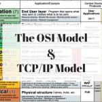
The Open Systems Interconnection (OSI) model is a conceptual framework consisting of seven layers.
The seven OSI layers
7
Application
Services used by applications
HTTP, DNS
6
Presentation
Data representation, encoding and encryption concepts
TLS-related functions, formats
5
Session
Dialog and session management concepts
Application session control
4
Transport
End-to-end transport and ports
TCP, UDP
3
Network
Logical addressing and routing
IPv4, IPv6, routers
2
Data Link
Local frames, MAC addresses and link access
Ethernet, Wi-Fi MAC
1
Physical
Signals, media and bits
Copper, fibre, radio
A common memory aid, from Layer 7 down to Layer 1, is:
All People Seem To Need Data Processing.
This stands for Application, Presentation, Session, Transport, Network, Data Link and Physical.
3. Understanding each OSI layer
Layer 7 — Application
This is the layer closest to the applications that use network services.
Examples include HTTP and DNS. When your browser requests a webpage, HTTP defines the application-level request and response semantics.
Important distinction: the OSI Application layer is not the same as the entire browser or the operating system's application.
Layer 6 — Presentation
This layer describes how data is represented, encoded, compressed or encrypted.
Examples of relevant concepts include character encoding, data formats and encryption-related transformations. Real TCP/IP implementations do not always implement these as a separate layer; TLS, for example, operates between application protocols and transport services.
Layer 5 — Session
This layer describes establishing, managing and terminating communication sessions.
Session functions are often integrated into applications and protocols rather than implemented as a distinct OSI layer in modern networks.
Layer 4 — Transport
The transport layer supports communication between processes running on hosts.
Two important protocols are:
TCP: connection-oriented transport with sequencing, acknowledgements and retransmission.
UDP: connectionless datagram transport with less built-in overhead and no delivery guarantee.
Transport ports help the receiving system deliver data to the correct application or service.
Layer 3 — Network
The network layer provides logical addressing and routing between networks.
Examples include IPv4 and IPv6. Routers use destination IP addresses and routing tables to determine where to forward packets.
Layer 2 — Data Link
This layer handles delivery over a local link. Ethernet and Wi-Fi define link-layer mechanisms, including framing and MAC addressing.
Switches commonly forward Ethernet frames using MAC address tables.
Layer 1 — Physical
This layer concerns the physical transmission of bits, such as electrical signals on copper, light in fibre or radio signals over Wi-Fi.
Physical-layer problems can include damaged cables, interference, poor signal strength or incorrect speed and duplex settings.
4. What is the TCP/IP model?
The TCP/IP model is the practical architectural model associated with the internet protocol suite.
A common four-layer version is:
TCP/IP layer
Main responsibility
Example protocols or technologies
Application
Application-level communication
HTTP, DNS, SMTP, DHCP
Transport
Process-to-process transport
TCP, UDP
Internet
Logical addressing and routing
IPv4, IPv6, ICMP
Network Access / Link
Local link communication and transmission
Ethernet, Wi-Fi
Some textbooks use a five-layer teaching model by separating the Physical layer from the Data Link layer. Both are useful; just be clear which model you're using.
5. TCP/IP versus OSI
OSI model
Common TCP/IP equivalent
Application (7)
Application
Presentation (6)
Application
Session (5)
Application
Transport (4)
Transport
Network (3)
Internet
Data Link (2)
Network Access / Link
Physical (1)
Network Access / Link
The mapping is approximate. The models were developed for different purposes, so not every function maps perfectly between layers.
Why should you learn both?
OSI gives you a detailed vocabulary for diagnosing network problems.
TCP/IP helps you understand the actual protocol architecture used on modern networks.
Together, they help you identify whether a fault is likely related to an application, transport connection, IP route, local link or physical medium.
6. Real-world troubleshooting example
Suppose a computer cannot open a website.
Observation
Possible layer or area to investigate
Network cable disconnected
Physical
Wrong VLAN or MAC learning problem
Data Link
Wrong IP address, mask or gateway
Network / Internet
TCP connection to the service fails
Transport
DNS cannot resolve the hostname
Application protocol / configuration
Server returns an HTTP error
Application
These are diagnostic clues, not absolute rules. For example, a DNS failure may be caused by a routing problem, a blocked UDP/TCP port, or an unavailable DNS server.
The lesson is to test each part of the communication path rather than randomly changing settings.
Lesson 15. TCP/IP Model: Where Are the Devices and Protocols?
Now that you understand the models, let's connect them to the devices and protocols you'll encounter as a network engineer.
1. Where do common network devices operate?
Router — mainly Layer 3
A router examines network-layer information, especially destination IP addresses, to select a route between networks. A router also operates at lower layers on each interface.
Ethernet switch — mainly Layer 2
A typical Layer 2 switch learns source MAC addresses and forwards Ethernet frames based on its MAC address table. Multilayer switches can also route at Layer 3.
Wireless access point — mainly Layer 2 bridging
It connects wireless clients to a local network and uses radio transmission at the physical layer. Some access points also offer routing, firewalling or other functions.
Computer or server — multiple layers
A computer runs applications, transport protocols, IP, link-layer protocols and physical interfaces. It does not belong to only one OSI layer.
Remember: a device can perform functions at several layers. The layer usually named for a device describes its main forwarding or networking function, not everything it does.
2. Where do common protocols fit?
Protocol or technology
Typical layer
Purpose
HTTP / HTTPS
Application
Web communication
DNS
Application
Resolves domain names to records such as IP addresses
DHCP
Application
Automatically configures IP settings
SMTP
Application
Transfers email
TCP
Transport
Reliable, ordered byte-stream delivery
UDP
Transport
Datagram delivery without TCP-style reliability
IPv4 / IPv6
Internet / Network
Addressing and routing
ICMP
Internet / Network
Error reporting and diagnostic messages
Ethernet
Link and physical functions
Local network framing and transmission
Wi-Fi
Link and physical functions
Wireless local networking
ARP
Between IP and link-layer functions in IPv4 networks
Resolves local IPv4 next-hop addresses to MAC addresses
ARP is often described as a Layer 2 protocol, although it bridges the functions of IP and the local link. Its exact placement in a simplified teaching model varies.
Your laptop compares the destination with its own subnet and determines that the server is remote.
It then prepares the traffic for delivery to the default gateway.
The important addresses are:
Source IP: 192.168.1.10
Destination IP: 203.0.113.20
Destination MAC on the first Ethernet/Wi-Fi link: the gateway's local interface MAC address, assuming the gateway is the next hop.
The destination IP generally remains the server's IP as the packet travels through routers, unless a function such as NAT changes it. The link-layer source and destination addresses are updated for each routed link.
This distinction is essential: the IP packet is addressed to the remote destination, while the local frame is addressed to the next hop.
4. Ports identify applications
Imagine two applications running on the same computer:
A browser communicating with a web server.
An SSH client communicating with a remote server.
Both may use the same source IP address, but transport ports distinguish the conversations.
Common examples:
Service
Common transport port
HTTP
TCP 80
HTTPS
TCP 443
SSH
TCP 22
DNS
UDP 53 and TCP 53
DHCP for IPv4
UDP 67 and 68
Ports identify transport endpoints, not individual devices. Port numbers are not always exclusive to a single application, and actual service configuration can differ.
Check your understanding
If a router sends a packet from one IP network to another, which address does it primarily examine to select a route?
Answer: The destination IP address, together with its routing table and other forwarding rules.
Lesson 16. TCP/IP Model: PDUs, Encapsulation and Decapsulation
This lesson explains how data is prepared for transmission and then reconstructed at the receiving end.
1. What is a PDU?
PDU means Protocol Data Unit. It is the unit of data associated with a particular protocol or layer.
In a common networking teaching model, the names are:
Layer
Common PDU name
Application
Data or message
Transport
TCP segment or UDP datagram
Internet / Network
IP packet
Data Link
Frame
Physical
Bits or transmitted symbols
Some textbooks use slightly different terminology. A PDU is a way of describing data at a particular protocol layer, not a separate file created by the computer.
2. What is encapsulation?
Encapsulation happens when data moves down the protocol stack toward the network interface.
Each layer uses its protocol to add the information needed for its function.
For example, when an application sends data using HTTP over TCP/IP and Ethernet:
The application creates the application data.
TCP adds a transport header, including source and destination ports.
IP adds a network header, including source and destination IP addresses.
Ethernet adds a frame header and trailer, including local MAC addressing and an error-detection field.
The interface transmits the resulting frame as physical signals or symbols.
Visualising encapsulation
1. Application data
HTTP message / application data
2. TCP segment
TCP header
Application data
3. IP packet
IP header
TCP header
Data
4. Ethernet frame
Ethernet header
IP packet and payload
FCS
Simplified illustration: exact frame fields and payload contents depend on the protocol and link type.
The headers are not all the same. Each protocol adds fields that are meaningful to that protocol.
For instance:
The TCP header includes ports and sequence information.
The IP header includes source and destination IP addresses.
The Ethernet header includes local source and destination MAC addresses.
The Ethernet FCS helps detect corruption of the frame.
3. What is decapsulation?
Decapsulation happens at the receiving system as data moves up the stack.
The receiving network interface accepts a frame, the link layer processes it, IP processes the network packet, TCP or UDP processes the transport information, and the application receives its data.
The receiving computer does not simply remove every header blindly. Each layer examines its relevant fields, validates what it can, and passes the appropriate payload to the next layer.
4. Example: sending a web request
Suppose your laptop opens an HTTPS website.
The application creates an HTTPS request.
TCP provides a transport connection in a typical HTTPS-over-TCP connection.
IP provides logical addressing.
Ethernet or Wi-Fi carries the IP packet over the local link.
The receiving server processes the traffic and returns a response.
A key modern detail: HTTPS can use HTTP/3 over QUIC, which uses UDP instead of TCP. Therefore, not all HTTPS traffic follows the TCP encapsulation example.
5. What changes when a router forwards a packet?
A typical router:
Receives a link-layer frame.
Processes the incoming frame and extracts the IP packet.
Examines the destination IP and routing/forwarding information.
Decreases the IPv4 TTL (Time To Live) by at least one; if it reaches zero, the packet is discarded and an ICMP Time Exceeded message may be sent.
Creates a new link-layer frame appropriate for the outgoing interface.
The source and destination MAC addresses usually change at each routed Ethernet hop. The source and destination IP addresses generally remain the same, except when translation or other processing changes them.
This is why the Ethernet header seen on your laptop's LAN is not necessarily the Ethernet header used at the remote server's LAN.
Lesson 17. TCP/IP Model: Packet Tracer Lab
Now let's put the theory into practice using Cisco Packet Tracer.
Packet Tracer is a network simulation and learning tool. It allows you to connect virtual PCs, switches and routers, configure IP addresses, and observe packets without needing physical hardware.
Lab objective
Create a small network containing two PCs connected to a switch. Assign both PCs addresses in the same subnet, then test communication.
PC0
192.168.1.10/24
Switch0
Layer 2 switching
PC1
192.168.1.20/24
Step 1: Build the topology
In Packet Tracer:
Add two PCs.
Add one Ethernet switch, such as a 2960.
Connect each PC's Ethernet interface to a switch port using copper straight-through cables. Packet Tracer may also automatically select the appropriate cable type.
Wait for the interfaces to become active.
No router is required because both PCs will be on the same IP subnet.
Step 2: Configure PC0
Open PC0, go to Desktop → IP Configuration, and enter:
Setting
Value
IP address
192.168.1.10
Subnet mask
255.255.255.0
Default gateway
Leave blank for this lab
Step 3: Configure PC1
Use the following settings:
Setting
Value
IP address
192.168.1.20
Subnet mask
255.255.255.0
Default gateway
Leave blank for this lab
Both PCs belong to 192.168.1.0/24.
Step 4: Test communication
On PC0, open Desktop → Command Prompt and run:
ping 192.168.1.20
You should receive replies once the interfaces are active and address resolution is complete. The first ping can occasionally time out while ARP resolves the destination MAC address.
Step 5: Observe the protocol stack
Switch Packet Tracer from Realtime to Simulation mode.
Use Add Simple PDU, often shown as an envelope icon.
Click PC0, then PC1.
Use Capture/Forward to step through the simulated exchange.
Select an event and inspect the OSI Model and PDU Details views.
Look for ARP resolution followed by ICMP echo request and echo reply traffic. A simple PDU is a diagnostic simulation, not an actual web request, but it is excellent for learning the networking layers.
Step 6: Create a fault deliberately
Change PC1's IP address to:
192.168.2.20
Keep its mask at 255.255.255.0.
Try pinging again from PC0.
The PCs now believe they are on different IP subnets. Because this lab has no router or default gateway, the ping should fail.
Restore PC1 to 192.168.1.20 and confirm communication works again.
What did you learn?
The switch can forward frames within the same LAN.
An IP address and mask determine subnet membership.
ARP resolves local IPv4 next-hop addresses to MAC addresses.
ICMP can test IP reachability.
Different IP subnets generally require a router or Layer 3 device to communicate.
Lesson 18. TCP/IP Model: Real-World Wireshark Lab
Packet Tracer teaches you how a network behaves in a simulation. Wireshark lets you inspect real packets and protocol exchanges on your computer.
Wireshark is widely used by network engineers, system administrators, security analysts and incident responders.
1. What is Wireshark?
Wireshark is a network protocol analyzer. It captures packets from a selected network interface and displays the protocol fields it can decode.
You can use it to investigate:
DNS lookup failures.
TCP connection problems.
HTTP requests and responses.
DHCP address assignment.
ARP resolution.
ICMP ping traffic.
Retransmissions and connection resets.
Unexpected or suspicious traffic.
Important: A capture only shows the traffic visible to the selected interface. On switched networks, your computer normally does not see all unicast traffic between other devices unless you have an appropriate capture point, mirror port, tap or other authorised visibility mechanism.
2. Install Wireshark on Kali Linux
If it is not already installed, open your terminal:
sudo apt update
sudo apt install wireshark
Launch it with:
wireshark
On Kali, capturing packets may require appropriate permissions or configuration. Avoid running graphical applications as root unless there is a specific reason. You can use the distribution's supported capture-permission setup or capture with authorised privileges.
Only capture traffic on networks and devices you own or are authorised to monitor.
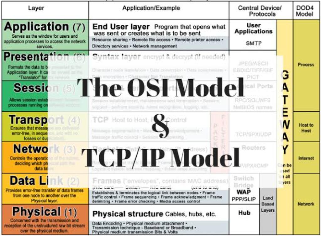
Example of the Wireshark interface. Your version and displayed packets may look different.
Follow these steps:
Open Wireshark.
Select the interface carrying your traffic, such as Ethernet or Wi-Fi.
Start capturing.
Open a browser or run a network test in a separate terminal.
Stop the capture after a short test.
Select a packet and expand its protocol fields in the packet details pane.
You will normally see a packet list with fields such as time, source, destination, protocol, length and information.
4. Lab A: Capture an ICMP ping
Open a terminal and run:
ping -c 4 1.1.1.1
In Wireshark, use this display filter:
icmp
On a network where the destination is reachable and ICMP is permitted, you may see:
ICMP Echo Request — sent by your computer.
ICMP Echo Reply — returned by the destination.
Expand the IP header and inspect the source and destination IP addresses. Then expand ICMP and look at the message type.
A ping failure does not always mean the network is down. The destination or a firewall may block ICMP, so also test DNS and application connectivity when troubleshooting.
5. Lab B: Inspect DNS
In Wireshark, use:
dns
Then run:
nslookup example.com
Look for a DNS query and its response if your interface captures the exchange.
Inspect:
The queried name.
The query type, such as A for IPv4 or AAAA for IPv6.
The DNS server address.
The response records or any error information.
If the query uses encrypted DNS, such as DNS over HTTPS, a simple DNS display filter may not reveal the underlying query name. The visible traffic depends on the DNS transport being used.
6. Lab C: Inspect TCP connections
Use this display filter:
tcp
Look for a connection between your computer and a remote server. Expand the TCP header to inspect source and destination ports, flags, sequence numbers and acknowledgement numbers.
A typical TCP connection establishment uses a three-way handshake:
SYN — the client requests to establish a connection.
SYN-ACK — the server acknowledges and responds.
ACK — the client acknowledges the response.
You may see these flags as SYN, SYN, ACK and ACK in Wireshark.
If the SYN is repeatedly retransmitted without a response, investigate the route, firewall, destination service and return path. A capture alone does not prove which component is responsible.
7. Lab D: Understand HTTP versus HTTPS
Try this display filter:
http
You may see HTTP requests if your test uses unencrypted HTTP and the traffic is captured.
For HTTPS, the application content is normally encrypted. You may see TLS handshake information and connection metadata, but you generally cannot read the HTTP request and response bodies without appropriate decryption keys and a supported decryption setup.
This is an important security lesson: packet capture can reveal useful connection information without automatically revealing encrypted application data.
8. Wireshark display filters to memorise
Filter
What it shows
arp
ARP packets
icmp
ICMP packets
dns
Recognised DNS traffic
tcp
TCP packets
udp
UDP packets
dhcp
DHCP traffic in current Wireshark versions
ip.addr == 192.168.1.10
IPv4 packets with that source or destination
tcp.port == 443
TCP packets using port 443
tcp.flags.syn == 1
TCP packets with the SYN flag set
A display filter controls which captured packets are shown; it does not remove other packets from the capture. A capture filter, by contrast, determines which traffic is collected in the first place.
Section 4 checkpoint
Before continuing, make sure you can explain:
What each OSI layer does.
How TCP/IP maps to the OSI model.
The difference between a frame, packet and segment.
Why MAC addresses change across routed Ethernet links.
How to capture ICMP, DNS and TCP traffic in Wireshark.
Section 5 — Binary
Binary is the foundation of digital computing and IPv4 subnetting. You don't need to become a mathematician, but you must become comfortable with powers of two, place values and converting between decimal and binary.
Lesson 19. Binary Introduction
1. What is binary?
Binary is a number system that uses only two digits:
0
1
Computers use digital electronic states to represent information. At a simplified level, those states are represented as zeros and ones.
A single binary digit is called a bit.
Examples:
0 = one bit.
1 = one bit.
1010 = four bits.
11000000 = eight bits.
Eight bits make one byte. In IPv4 addressing, eight-bit groups are called octets.
2. Decimal versus binary
The decimal number system uses ten digits, from 0 to 9, and is based on powers of 10.
Binary uses two digits and is based on powers of 2.
In decimal, the number 345 means:
\[ 3(100)+4(10)+5(1)=345 \]
In binary, the number 1011 means:
\[ 1(8)+0(4)+1(2)+1(1)=11 \]
Therefore, binary 1011 equals decimal 11.
3. Binary place values
For an eight-bit number, the place values are:
128
64
32
16
8
4
2
1
Each position is twice the value of the position immediately to its right.
Memorise this sequence:
128, 64, 32, 16, 8, 4, 2, 1
The leftmost bit is the most significant bit (MSB). The rightmost is the least significant bit (LSB).
4. How to calculate a binary number
Let's convert 00001101 into decimal.
Bit
Place value
Contribution
0
128
0
0
64
0
0
32
0
0
16
0
1
8
8
1
4
4
0
2
0
1
1
1
Add the contributions:
\[ 8+4+1=13 \]
So:
00001101 = decimal 13.
The zeros are important for keeping the number aligned to eight bits, especially when working with IPv4 addresses.
5. Why binary matters to network engineers
Binary helps you understand:
Why each IPv4 octet ranges from 0 to 255.
How subnet masks divide network and host bits.
How routers and computers compare network prefixes.
How TCP flags and other protocol fields are represented.
How to interpret fields inside packet captures.
When you learn binary well, subnetting becomes much easier.
Lesson 20. Binary Math
You should understand both binary place values and the basic arithmetic operations used with binary numbers.
1. Binary addition
Binary addition follows four basic rules:
Calculation
Result
0 + 0
0
0 + 1
1
1 + 0
1
1 + 1
10
Why does 1 + 1 = 10 in binary?
Because 10 in binary means decimal 2. Just as decimal addition carries when a column reaches 10, binary addition carries when a column reaches 2.
Example:
   0101   (5)
 + 0011   (3)
 ------
   1000   (8)
So binary 0101 + 0011 = 1000, which is decimal 8.
2. Binary subtraction
The basic rules include:
0 - 0 = 0
1 - 0 = 1
1 - 1 = 0
0 - 1 requires borrowing.
Example:
   1000   (8)
 - 0011   (3)
 ------
   0101   (5)
Borrowing in binary can take more practice than addition. For networking, binary conversion and bitwise operations are generally more immediately useful than lengthy binary subtraction.
3. Binary multiplication
Binary multiplication follows these simple rules:
0 × 0 = 0
0 × 1 = 0
1 × 0 = 0
1 × 1 = 1
Example:
   101   (5)
 x  10   (2)
 -----
   000
  101
 -----
  1010   (10)
Binary 1010 equals decimal 10.
4. Bitwise AND
For networking, bitwise AND is especially important because it is used to calculate an IPv4 network address from an IP address and a subnet mask.
The rules are:
A
B
A AND B
0
0
0
0
1
0
1
0
0
1
1
1
Only two 1 bits produce a 1.
Consider the final octet of an IP address and mask:
For an entire IP address, you perform this operation on all 32 bits.
5. Bitwise OR and XOR
OR produces 1 when at least one input bit is 1.
XOR produces 1 when the input bits differ.
A
B
OR
XOR
0
0
0
0
0
1
1
1
1
0
1
1
1
1
1
0
These operations are important in programming, protocol processing and low-level network analysis, although subnet calculations rely particularly heavily on AND.
6. Try the binary calculator
Interactive bitwise calculator
First binary number (up to 8 bits)
Operation
AND
OR
XOR
Second binary number
Result in binary
10100000
Result in decimal: 160
Lesson 21. Binary Conversion Examples
You need to learn how to convert decimal numbers into binary and binary numbers back into decimal.
There are two main methods:
The place-value method.
The repeated division-by-two method.
Method 1: Binary to decimal
Convert 101101 to decimal.
Write down the place values from right to left:
Bit
Place value
Contribution
1
32
32
0
16
0
1
8
8
1
4
4
0
2
0
1
1
1
Add the values where the bit is 1:
\[ 32+8+4+1=45 \]
Answer: binary 101101 = decimal 45.
For an eight-bit number, simply add the place values corresponding to the 1 bits.
Method 2: Decimal to binary using division
Convert decimal 45 into binary.
Repeatedly divide by 2 and record each remainder.
Calculation
Quotient
Remainder
45 ÷ 2
22
1
22 ÷ 2
11
0
11 ÷ 2
5
1
5 ÷ 2
2
1
2 ÷ 2
1
0
1 ÷ 2
0
1
Read the remainders from bottom to top:
101101
Therefore, decimal 45 = binary 101101.
As an eight-bit octet, write it as 00101101.
Method 3: The place-value selection method
This method is often faster for networking because the place values are always the same.
Convert decimal 200 to binary.
Start with the place values:
128 64 32 16 8 4 2 1
200 is at least 128: set the first bit to 1. Remainder: 72.
72 is at least 64: set the second bit to 1. Remainder: 8.
8 is less than 32 and 16: those bits are 0.
8 is equal to 8: set that bit to 1. Remainder: 0.
The remaining bits are 0.
The result is:
11001000
Check:
\[ 128+64+8=200 \]
Interactive conversion practice
Convert a number
Decimal → Binary
Binary → Decimal
Decimal number (0–255)
Convert
Common binary conversion mistakes
Reading remainders from top to bottom instead of bottom to top.
Forgetting that the rightmost bit has value 1.
Confusing the bit value with its place value.
Omitting leading zeros when writing an IPv4 octet.
Assuming every binary number must contain exactly eight bits outside an octet context.
Lesson 22. Converting IP Addresses to Binary
This lesson connects binary mathematics directly to networking.
Every IPv4 address has four decimal octets, and every octet can be represented as eight bits.
1. Example: convert 192.168.1.10
Convert each octet independently.
Decimal octet
Binary octet
192
11000000
168
10101000
1
00000001
10
00001010
The full binary address is:
11000000.10101000.00000001.00001010
Check each octet:
11000000 = 128 + 64 = 192.
10101000 = 128 + 32 + 8 = 168.
00000001 = 1.
00001010 = 8 + 2 = 10.
This is the binary representation of 192.168.1.10.
2. Convert an IP address and subnet mask
Suppose you have:
IP address: 192.168.1.10
Subnet mask: 255.255.255.0
Their binary representations are:
IP address:
11000000.10101000.00000001.00001010

Subnet mask:
11111111.11111111.11111111.00000000
The first 24 bits belong to the network, and the last 8 bits belong to the host.
Its broadcast address is 192.168.1.127, and the conventional usable host range is 192.168.1.65–192.168.1.126.
Why? The last octet of the subnet begins at 64 and spans 64 addresses, through 127.
4. Practice: find the binary representation
IPv4 binary converter
Enter an IPv4 address. Each octet is converted into eight bits.
Octet 1
Octet 2
Octet 3
Octet 4
Convert IP address
Section 5 checkpoint
You should now be able to convert numbers between decimal and binary, explain the eight-bit place values, and calculate an IPv4 network address by applying a subnet mask in binary.
Section 6 — Hexadecimal
Lesson 23. Hexadecimal: Why Do We Care?
1. What is hexadecimal?
Hexadecimal, often called hex, is a base-16 number system.
Decimal uses ten digits:
0 1 2 3 4 5 6 7 8 9
Hexadecimal uses sixteen symbols:
0 1 2 3 4 5 6 7 8 9 A B C D E F
The letters represent values greater than 9:
Decimal
Hexadecimal
0–9
0–9
10
A
11
B
12
C
13
D
14
E
15
F
After F, the next hexadecimal number is 10, which equals decimal 16.
This is similar to how decimal advances from 9 to 10, except hexadecimal advances from F to 10.
2. Why do network engineers use hexadecimal?
Computers ultimately represent digital information using bits, but binary strings can be long and difficult for humans to read.
Consider this 32-bit value:
11000000101010000000000100001010
It is much easier to read in hexadecimal:
C0A8010A
Both represent the same 32-bit value.
Hexadecimal makes it easier to represent and inspect:
MAC addresses.
IPv6 addresses.
Ethernet frame fields.
Packet headers and protocol flags.
Memory and binary data in diagnostic tools.
Cryptographic values and other data displayed by networking utilities.
Hexadecimal is not a replacement for binary. It is a compact way of expressing binary values.
3. The relationship between binary and hexadecimal
One hexadecimal digit represents exactly four binary bits.
This four-bit group is called a nibble.
Binary nibble
Hex
Decimal
0000
0
0
0001
1
1
0010
2
2
0011
3
3
0100
4
4
0101
5
5
0110
6
6
0111
7
7
1000
8
8
1001
9
9
1010
A
10
1011
B
11
1100
C
12
1101
D
13
1110
E
14
1111
F
15
Memorise the final six entries. Once you know that 1010 = A and 1111 = F, binary-to-hex conversion becomes much easier.
4. Hexadecimal and IPv4
Take this IPv4 address:
192.168.1.10
Its four octets can be expressed in hexadecimal:
Decimal
Binary
Hexadecimal
192
11000000
C0
168
10101000
A8
1
00000001
01
10
00001010
0A
The full 32-bit hexadecimal value is:
C0A8010A
You may encounter this representation in packet analysis, programming and networking documentation. IPv4 addresses are normally written in dotted-decimal notation, however.
5. Hexadecimal and MAC addresses
A MAC address is commonly represented as six pairs of hexadecimal digits.
Example:
00:1A:2B:3C:4D:5E
Each pair represents one byte, or eight bits.
The complete address is 48 bits long:
\[ 6 \times 8 = 48 \text{ bits} \]
Why hexadecimal? Each byte can be represented by two hex digits, making the address much easier to read than 48 binary digits.
MAC addresses are link-layer addresses. Their use and scope depend on the network technology and address type; a MAC address should not be confused with a globally routable IP address.
6. Hexadecimal and IPv6
IPv6 addresses use hexadecimal groups separated by colons.
Example:
2001:0db8:0000:0000:0000:ff00:0042:8329
Each group contains up to four hex digits, representing 16 bits.
IPv6 uses 128 bits in total:
\[ 8 \times 16 = 128 \text{ bits} \]
Leading zeros within a group can be omitted, and consecutive all-zero groups can be compressed using :: once within an address.
The example above can be shortened to:
2001:db8::ff00:42:8329
The 2001:db8::/32 range is reserved for documentation, so this is an example rather than an ordinary public destination.
Lesson 24. Hexadecimal: Lab Demonstration
Let's practise converting between hexadecimal, binary and decimal, then connect the concepts to real network tools.
Lab A: Convert hexadecimal to decimal
Consider hexadecimal 2F.
Each hexadecimal position is a power of 16.
The rightmost position has value \(16^0=1\).
The next position has value \(16^1=16\).
So:
\[ 2F_{16}=2(16)+15=47_{10} \]
Therefore, hexadecimal 2F equals decimal 47.
Another example:
\[ A5_{16}=10(16)+5=165_{10} \]
Lab B: Convert decimal to hexadecimal
Convert decimal 200 to hexadecimal.
Divide by 16:
\[ 200 = 12(16)+8 \]
Decimal 12 is C in hexadecimal.
Therefore:
200 decimal = C8 hexadecimal.
Check:
\[ 12(16)+8=200 \]
Lab C: Convert binary to hexadecimal
Convert this binary number:
11000000
Split it into two four-bit groups:
1100 0000
Convert each nibble:
1100 = C
0000 = 0
Therefore:
11000000 binary = C0 hexadecimal.
Now try another:
10101000
Split it:
1010 1000
1010 = A
1000 = 8
Result: A8.
This is why 192.168.1.10 can be represented as C0.A8.01.0A when each octet is converted separately.
Lab D: Inspect a MAC address on Kali Linux
Run:
ip link show
Look for a line similar to:
link/ether 00:1a:2b:3c:4d:5e
Your actual MAC address will probably be different. The displayed value is an example.
You can also inspect your IPv4 configuration:
ip -4 addr show
This lets you compare the logical IPv4 address with the link-layer MAC address.
Lab E: Inspect hexadecimal in Wireshark
Open Wireshark and select a permitted network interface.
Capture a few packets.
Select one packet in the packet list.
Look at the packet bytes pane, which displays hexadecimal values alongside their ASCII interpretation where applicable.
Select a protocol field in the packet details pane and observe the corresponding bytes being highlighted.
For example, an Ethernet frame contains a destination MAC address and a source MAC address in its header, followed by a field indicating the payload type or length.
The byte display lets you see the actual encoded values rather than only their interpreted labels.
Do not assume every byte in a capture is plaintext. TLS and other encryption mechanisms can make application content unreadable without authorised decryption.
Lesson 25. Hexadecimal Calculations
This lesson develops your ability to add, multiply and convert hexadecimal values. These skills are useful when reading packet dumps, working with binary data, understanding IPv6 and troubleshooting protocols.
1. Hexadecimal place values
Hexadecimal uses powers of 16.
Position
Place value
1st digit from the right
\(16^0=1\)
2nd digit from the right
\(16^1=16\)
3rd digit from the right
\(16^2=256\)
4th digit from the right
\(16^3=4096\)
For example, convert 3B7 to decimal.
3 represents 3 hundreds in base 16: \(3\times256=768\).
B represents 11: \(11\times16=176\).
7 represents 7: \(7\times1=7\).
Add them:
\[ 768+176+7=951 \]
Therefore:
\[ \boxed{3B7_{16}=951_{10}} \]
2. Hexadecimal addition
Let's calculate:
   2A
 + 17
 ----
Convert to decimal to understand the result:
2A = 42.
17 = 23.
Total = 65.
Decimal 65 equals hexadecimal 41.
Therefore:
   2A
 + 17
 ----
   41
The hexadecimal addition works because A (10) plus 7 equals 17 decimal, which is 11 in hexadecimal. Write the 1 in the rightmost position and carry 1 to the next column.
Then 2 + 1 + 1 = 4, giving 41.
3. Hexadecimal multiplication
Consider:
\[ A_{16}\times 4_{16} \]
A represents decimal 10, so:
\[ 10\times4=40 \]
Decimal 40 is hexadecimal 28.
Therefore:
\[ A_{16}\times4_{16}=28_{16} \]
You can always verify a hexadecimal calculation by converting the operands and result to decimal.
4. Convert an IPv4 address to hexadecimal
Let's convert 10.0.0.1.
Each octet is converted separately:
Decimal
Hexadecimal
10
0A
0
00
0
00
1
01
Combined as a 32-bit hexadecimal value:
0A000001
This is useful when comparing IPv4 values represented as raw bytes, although normal IPv4 configuration uses dotted-decimal notation.
5. Understand hexadecimal in IPv6
Consider:
2001:0db8:0000:0000:0000:0000:0000:0001
Every group represents 16 bits.
The leading zeros can be omitted, and the longest run of all-zero groups can be compressed once:
2001:db8::1
You should learn to recognise both the expanded and compressed forms as the same address.
6. Interactive hexadecimal converter
Decimal ↔ Hexadecimal
Decimal → Hex
Hex → Decimal
Decimal number (0–65535)
Convert
Final assessment: Sections 4, 5 and 6
Test yourself on all three sections. Try to answer before checking your result.
Networking knowledge test
0/10 answered
1. Which OSI layer is mainly responsible for routing between IP networks?
Layer 1 — Physical
Layer 2 — Data Link
Layer 3 — Network
Layer 7 — Application
2. What is the correct PDU name commonly used for TCP data?
Frame
Segment
Bit
Signal
3. Which protocol resolves a local IPv4 next-hop address to a MAC address?
DNS
DHCP
ARP
HTTP
4. What is the decimal value of binary 11001000?
128
192
200
220
5. What is 45 in eight-bit binary?
00101101
00110101
01001101
00101011
6. What is the binary result of 1010 AND 1100?
1110
1000
0110
0010
7. How many bits are in one hexadecimal digit?
2
4
8
16
8. What is hexadecimal C8 in decimal?
188
192
200
208
9. What is hexadecimal F in decimal?
10
12
14
15
10. What does Wireshark primarily do?
Assigns IP addresses automatically
Captures and analyses network packets
Replaces a router
Encrypts every network connection
Check answers
Your practical study plan
Hands-on checklist
0/6 completed
Explain the seven OSI layers without looking at your notes.
Build the two-PC Packet Tracer lab and successfully ping between the PCs.
Capture ICMP, DNS and TCP traffic in Wireshark.
Convert 10 decimal numbers between binary and decimal.
Convert five hexadecimal values to decimal and binary.
Explain how a subnet mask uses binary AND to find a network address.
These topics are essential for Cisco networking, CCNA, AWS VPC networking, Linux administration, cybersecurity, and enterprise network design.
Our goal is not just to memorize IP addresses. By the end, you should be able to look at an IP address, calculate its network, identify its host range, determine the broadcast address, and understand how to divide a network into subnets.




![Wireshark user interface - Packet Analysis with Wireshark [Book]](https://images.openai.com/static-rsc-4/4hxt5YiTpOf2UP7rLR0W9pU8qp6LaZdHiOUBzNKEbr9eL8BI5APTiGakRsR2k0tNyJKHz_0XS6NcTwIrDy_XBjB0emU6uJDF5pb8lTJeyFeHF0m_-1HzKRCnwtf7QT_Ct0SafOD7dw5b3MWzoX0l5eCLZbUblDvuy5448dj421c?purpose=inline)